What World War 2 Planes Used the Collins Art 13 Transmitter
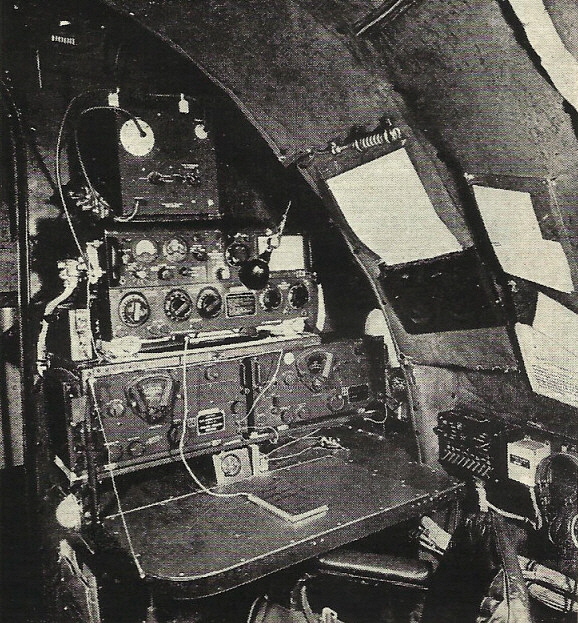
| Radio Boulevard Rebuilding the ART-xiii Transmitters Part 1 General Information about the Art-13 Selecting an ART-13 Candidate for Restoration Deciding How to Power the Fine art-13 information constitute in parts ii, three and 4,.... Restoration Hints and Suggestions "Basket Instance" Restoration Project & 3 Other Restoration Projects Building a Suitable Air-conditioning Power Supply (includes 3 Schematics) How to Setup and Operate the Fine art-13 Today Operating the ART-13 on LF 630M (472kc) by: Henry Rogers WA7YBS/WHRM | photo above: Radioman's position on a Douglas DC-iv using an Art-thirteen and ii BC-348 receivers - Radio News Jan 1950 |
When information technology comes to vintage WWII military radio transmitters, it'southward pretty hard to beat the Fine art-13. Information technology's a potent 100+ watt transmitter that doesn't "weigh a ton" and has the potential to provide first-class audio in the AM mode. On top of that, parts needed for a restoration are usually easy to notice and most of the circuitry is non too difficult to work on. Also, I've included construction data, including schematics, on iii unlike Fine art-13 AC power supplies that I've built. Certainly every restorer/operator has their own techniques and the prospective ART-13 owner should read everything available on the Internet almost these popular war machine transmitters to help them determine on a project that best suits their abilities and their goals. H. Rogers - May 10, 2011
|
|
Depression Frequency Coverage and More Accessories - The standard Art-13 transmitter frequency range is from 2.0mc to eighteen.0mc, however many Navy ATC and T-47/Fine art-thirteen transmitters and afterward USAAF T-47A/ART-13A transmitters were equipped with a plug-in Low Frequency Oscillator (LFO) module that allowed the transmitter to operate from 200kc to 600kc or 200kc to 1500kc (at somewhat reduced power, CW only for electrically curt antennae.) Early LFOs had a frequency range of 200kc to 1500kc in half dozen ranges designated as O-16/Art-13, while the later on LFOs embrace 200kc to 600kc in three ranges and is designated every bit O-17/ART-13A. The LFO modules used a unmarried 1625 tube. If 630 meter operation is desired then be aware that the O-16 LFO "splits" the 630 meter band with a range alter at 475kc. There's enough "overlap" to cover the entire 630 meter ring at the edge of either range selected. When the LFO is in performance the Art-13 Multiplier department is bypassed and the LFO output directly drives the PA.
There are some indications that the Navy set-ups used the 200kc to 1500kc LFO while the USAAF used the 200kc to 600kc LFO. Near versions of the T-47/ART-13 will have a blank plate installed where the LFO module was installed designated as NX-128/ART-13. These LFO "dummy panels" had a resistive load included that substituted for the LFO'due south 1625 filament load. It's possible the nearly of the LFOs were removed afterwards in the Fine art-13'southward life as the transmitters were usually on HF afterward WWII. According to the USAF Extension Course 3012 book on "Radio Mechanics from 1950," the Navy was still using LF after WWII simply the USAAF wasn't.
When switched to LF, the ART-13 PA output is capacitively coupled (via the plate blocking capacitor) to "LOADING Coil" last J-117. Selecting the LF position also disconnects the ART-13 internal HF antenna matching network. The aircraft installations (when operating LF) would crave the CU-25 or CU-32 antenna tuners (called Antenna Loading Coils.) These units provided the antenna matching networks for low frequency functioning of 200kc upwards to 600kc. There was also the CU-26 that provided antenna matching for 500kc up to 1500kc. The CU-32 allows the utilise of either trailing wire or fixed antennae while the CU-25 and CU-26 are for abaft wire only. More often than not, the Navy used the CU-25 and CU-26 while the USAAF used the CU-32.
Too almost installations on aircraft included a small Remote Control Panel designated as C-87/ART-thirteen or a smaller remote designated as C-470/Fine art-xiii. The remotes allowed the pilot to operate the transmitter from the cockpit. The larger C-87/Art-13 has a paw push for keying the ART-thirteen and allows a microphone connection at the remote. A typical aircraft ART-13 installation could select from a couple of dissimilar remotes, 3 different types of LF antenna tuners, a triple fixed capacitor (CU-24 auxiliary capacitor for antenna loading below 7mc - each capacitor was 25pf in value for a maximum bachelor C of 75pf) forth with diverse antenna and capacitor-selecting knife switches. There were at least a couple of different daze mounts that were available depending on the version of ART-xiii and where it was located. Daze mounts provided vibration isolation and elevated the transmitter to allow convection cooling. Almost installations seen in vintage photographs usually have two BC-348 receivers. Later (unremarkably mail-WWII) aircraft installations may have the ARR-15 receiver.
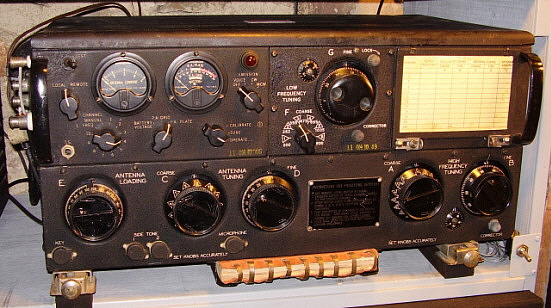
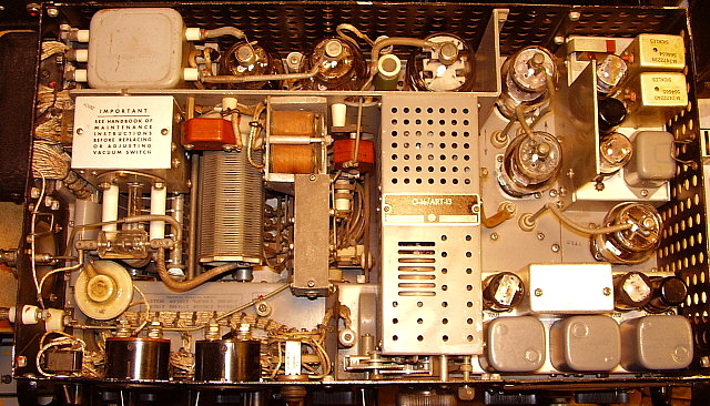
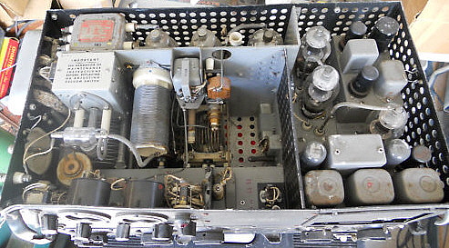
| | The Chassis Layout - To the left is a photo showing the chassis of an early on Collins-congenital T-47/ART-xiii. This transmitter has the Navy version LFO installed. Too, this is a fairly early version of the transmitter and so there are some differences when compared to the T-47A/Fine art-13 versions. Of note is the lack of an interlock switch which on the early versions allows y'all to easily operate the transmitter with the lid off. The module to the lower right is the Audio Amplifier unit and straight behind information technology is the 837 VFO tube. Behind the VFO tube is the FCI/MCW module and to the left of information technology are the two 1625 multiplier tubes. The module in the middle of the transmitter is the LFO. In the department at the rear of the transmitter, to the left side is the modulation transformer from which its plate leads connect to the two 811 modulator tubes. To the right of the 811s is the 813 PA tube. The left-heart section of the transmitter contains the matching network and the LF relay (side by side to the LFO module.) On the far left is the vacuum TR switch and backside information technology is the keying relay. The circular ceramic unit in forepart of the vacuum TR switch is the anterior pickup for the Antenna Electric current meter. T-47A/Art-13 or AN/Fine art-13A - The somewhat afterward USAAF T-47A/Art-13 aka: AN/ART-13A version added some minor improvements to the transmitter with a vernier scale on the VFO Fine Tuning, a top hat interlock switch, a dissimilar bottom plate with built-in guides for the daze mount and a white ceramic insulator bell on the antenna connectedness existence among the most apparent changes. This model of the transmitter is often found built by diverse contractors with Stewart-Warner (CWS) and Zenith (CZR) being the most often encountered (Zenith was an early contractor having built some of the ATC versions.) The contractor identification is most oftentimes found on the metal tag mounted on the correct side of the transmitter as initials incorporated into the serial number. Conversions/ MWOs - Almost all earlier ATC and early Art-13 will accept several MWO updates added to the transmitter. Information technology's common to notice that the FCI/MCW module is the later version, also that a hat interlock has been installed. Sometimes the later style base mount is installed. The MWO IDs are commonly stenciled on the right side of the transmitter with the letter "M" followed past a number from one to 6 identifying the MWO. Sometimes the original ATC information tag will be replaced with a T47/Art-13 tag. |
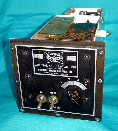
| | T-412/ART-13B or AN/Fine art-13B - There was likewise a T-412/Fine art-13B that added a 4 channel LF/MF and xx channel HF crystal oscillator module, the CDA-T in place of the LFO module. The CDA-T was built past Communications Visitor, Inc.(aka COMCO,) who generally supplied the module with a total installation kit that included extensive instructions and directions for the conversion of either the ATC, the T-47/ART-thirteen or the ART-13A. When the CDA-T was installed and the transmitter fully converted to the "B" version then, with the option of each of the transmitter channels 1 to 10, two dissimilar crystals could exist selected giving the user two frequencies per aqueduct or a full of 20 HF channels in all. As well with the CDA-T installation a "frequency extension" modification was added that changed the lower terminate of the frequency coverage down to 1670kc. The LF position allowed the selection of 4 crystal controlled frequencies on the CDA-T module. The remote used with the "B" version volition accept a toggle switch to allow selecting either crystal frequency per aqueduct selected. All "B" versions of the Art-thirteen are conversions of earlier ART-13 or ATC transmitters. Be aware that you lot can't just install the COMCO module and have your Art-thirteen get a "B version. In fact, the CDA-T tin can't even plug-in to an unmodified Fine art-13. The installation of the "B" version CDA-T module required extensive modification of the transmitter circuitry forth with the addition of a second Jones Plug for the module and an additional wafer for the REMOTE-LOCAL switch along with several boosted components (supplied in the kit with the module.) Most Fine art-13B conversions that were performed past the armed services during WWII will take riveted tags installed to place the frequency extension toggle switch and another tag riveted above the original transmitter data plate that identifies the conversion to T-412/ART-13B. Postal service-WWII conversions generally don't accept these riveted tags installed. Since in that location was no modification to the Autotune of the ART-13 transmitter, each of the A/B crystal channels had to be set very close in frequency to each other, otherwise the transmitter wouldn't be tuned for one or the other of the lettered crystal channels. photo left: The Crystal Oscillator Unit for the ART-13B. Built by Communications Company, Inc. (COMCO.) |
| Postal service-WWII Use - The T-47/Art-thirteen had a very long life. Introduced effectually 1942, actively used during and afterwards WWII and well into the sixties. The Grumman HU-sixteen air-sea rescue amphibians were equipped with ART-xiii/BC-348s until the late 1960s. The USSR besides produced a copy of the ART-13 that they used up to the tardily 1980s (the R-807.) Surprisingly, the ART-xiii was available on the surplus market place apace after WWII ended. By 1946, one could purchase an ART-13 with all of the accessories for between $75 and $125. Almost were fully checked out and guaranteed to piece of work. Many hams bought the Fine art-13 as a station transmitter, some operating the transmitter on its dynamotor while most congenital Ac power supplies instead. The availability changed adequately quickly and past 1950 only a few surplus dealers offered the ART-thirteen. Civilian airline companies besides began using the ART-13 in various commercial airliners. Many were converted to the B version for multiple crystal-command channels (in that location was also a C version which was similar in function.) Some ART-13s were supplied to civilian aircraft in new condition with priority sales which probably accounted for the shortage in the surplus market after 1950. Because of its long useful life, most T-47/ART-13 transmitters found today volition take many scratches and a few dents and several pigment scrapes. Nearly all transmitters encountered today will have been through various military depots for repairs or upgrades many times over its years of use. About transmitters will accept non-matching (updated) modules with some parts having MFP applied and others that are bare. Usually, the right side of the transmitter case volition have various MWO numbers stenciled to indicate what upgrades were installed (usually M1 through M6 were always installed on earlier transmitters.) Mis-matched meters are mutual to depot repairs. Nearly all war machine transmitters will have the Microphone switch prophylactic wired in the CARBON position unless information technology has been recently worked on by hams. A volume containing cursory instructions and the calibration settings for specific frequencies is usually stored in the metal pocket underneath the transmitter. Earlier versions of the transmitter will have a somewhat thinner (and ever missing) book non "chained" to the pocket. This earlier book is specifically for the ii tube version of the MCW/FCI module used in the ATC and early T-47 transmitters. After versions have a thicker volume that is specific for the three tube version of the MCW/FCI module used in late T-47 and all Fine art-13A versions. The afterwards volume has a plastic tubing covered chain that was supposed to keep the book "tied" to the transmitter. This later book is as well usually missing on most transmitters (although the aforementioned information is in the standard manuals.) Luckily, many tens of thousands of T-47/ART-xiii were congenital and spare parts are very easy to find which allows for the fairly easy restoration and maintenance of these durable and potent transmitters. |
|
Selecting an ART-13 Candidate for Restoration
Preliminary Considerations
Assessing your potential restoration candidate prior to purchase is of import for a successful completion of the project. Choosing the correct Art-thirteen is certainly going to determine how long information technology takes you to complete the project and become it "on the air." There are a couple of tests that should be made if you have admission to the transmitter before purchasing. Also, some things to look for when buying on line.
| Technical Difficulty of Restoring an Art-xiii - The ART-13 is a robustly-congenital just light-weight, compact transmitter. Since information technology is fairly modest most of the components are installed into tight quarters and accessing most of the transmitter circuitry volition crave some disassembly. Fortunately, most of the transmitter design and construction allows easy disassembly to admission and piece of work on various parts of the circuitry. If you have serious problems in the Autotune section, this is difficult to disassemble and some of the parts are somewhat frail. Same goes for the VFO-Multiplier sections which are hard to admission and the Multiplier uses very fragile stacked trimmer capacitors. Though the Sound and MCW/FCI modules are easy to remove, the components are densely mounted nether the chassis. Near ART-13s will have MFP applied and this volition chemical compound the difficulty of any soldering work that might be required. Certainly an AC power supply (if opt'd for) will be the most time consuming to design and build. >>> | >>> You lot should have the post-obit skills when taking on an ART-thirteen project. You should have some experience working on tube-type transmitters and working around high voltages. You should be experienced in total disassembly and reassembly of electronic equipment. If you lot decide on an AC power supply, you should possess "homebrewing" skills, that is, sail metal working, component layout, proper wiring dress, etc. You lot should take practiced technician skills, possess a adept soldering technique and use existent SnPb solder with first grade soldering equipment. You will need good quality examination equipment. You will need a prepare of spline wrenches (likewise called Bristol wrenches) for all set spiral applications. An oscilloscope is essential during testing and gear up up of the transmitter. You should possess good troubleshooting skills. Near hams that have worked on several tube-type transmitters and have built some radio equipment will accept the necessary skills to complete the restoration of an ART-thirteen. |
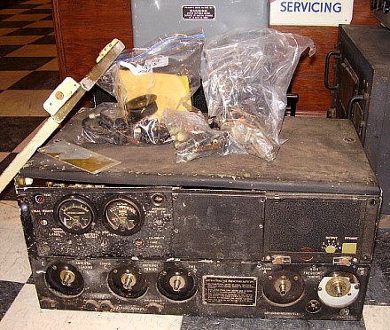
| Selecting a Candidate for Restoration - There are a lot of Fine art-thirteen transmitters for sale at bandy meets, on eBay, from Fair Radio Sales or from various online sources. Art-13s are not difficult to observe. Merely, what is difficult to find is a good condition, all original and complete ART-13. Most of the transmitters that are for sale await like the 1 in the photo to the right. Not a expert candidate unless you lot are experienced and looking for a real challenge*. This candidate's condition is obvious but many times the Fine art-13 you are looking at can have serious problems that aren't obvious at all. A thorough inspection followed past actually testing a couple of the components can aid "weed out" a transmitter that is going to demand a lot of repair and restoration work. A adept candidate should be fully assembled and have all of its modules installed. A few missing tubes are okay since they are easy to notice and not terribly expensive. Be aware though, missing tubes should be taken as an indicator that the transmitter was considered a "parts source" at one fourth dimension and may actually accept some operational problems - not e'er - but definitely investigate farther if allof the tubes are missing. Meters should be in good condition and they are easy to test while in the transmitter. The meters are not hard to locate but the same caveat as with missing tubes should be considered. Generally, a complete and practiced condition transmitter means it has always been stored correctly, has not been abused and probably has a pretty adept chance that cypher serious will exist institute wrong in the circuit or with the components. Be skeptical though! Even though the transmitter might look smashing, it could have a serious, hard to solve trouble that kept the transmitter from ever being used, thus it's excellent appearance. Definitely, any transmitter that is missing parts should be considered a "restoration projection" that is going to crave fourth dimension searching for parts and will demand more fourth dimension to get the fully operational. *Run into section below "T-47A/Fine art-thirteen 'Basket Case' Restoration" to see how this transmitter turned out. photo right: T-47A/Fine art-thirteen "parts prepare." Notation, even the multimeter glass is broken. Although restorable, this one would be a definite claiming. | |
Inspecting the ART-13 Before Purchase
| Thorough Inspection of the Transmitter - If y'all have admission to the transmitter prior to buy you can wait it over in detail. The two "easy to remove" modules should be present. The 3-tube MCW/FCI module is easy to notice if information technology's missing but the Audio module is more expensive and a picayune more difficult to locate. Check the interlock switch on the T-47A/ART-xiii versions since if the transmitter is placed upside downwardly with the lid off (for quick and careless repair piece of work) more than than likely the switch will be cleaved. Check the wiring for anything cut or missing. >>> | >>> Bank check for broken parts. The Antenna vacuum switch is sometimes broken since information technology is a glass unit. Disengage the locking bars and see if the controls rotate hands. Don't "forcefulness" whatsoever controls that seem stuck - you'll only pause something. The controls should freely rotate. Check the status of the button connectors on the left side of the transmitter and make sure they aren't corroded and stuck. Too, cheque the condition of the U/7 connector and brand sure the pins aren't bent or corroded. That's about all you can bank check visually. If the seller is agreeable, bank check the Modulation Transformer and the Meters as described in the following sections. |
| Testing the Modulation Transformer - This is probably the most of import office of the transmitter that is sometimes missing and other times non-functional. Finding a good condition replacement (if you demand i) is difficult and somewhat expensive. You will want to know "up front" if the Fine art-13 you're contemplating buying has a non-operational modulation transformer as this will seriously affect its selling price. You lot'll need to have a DMM (Digital Multimeter) to check the modulation transformer. You will be measuring the DC resistance (DCR) of the windings. This test is not a 100% indication that the modulation transformer is perfect only it's a pretty good test. Besides, if the DCR of a tested winding reads open, you then know 100% for sure that the modern transformer is bad. Take intendance to make skillful contact to the terminals with your test probes, especially if the mod transformer is coated with MFP. Annotation that each of the seven terminals are numbered. The iii terminals on the left side (assuming you lot're in front of the transmitter) are from left to correct looking at this side 6, vii and 2. On the right side the four terminals are left to right 1 and 3 on top and iv and five on the bottom. Exist enlightened that the 813 screen windings accept a different DC resistance on early units. The change occurred about the middle of the Fine art-13A contracts. It looks similar the wire used for the the screen winding was increased in diameter for ameliorate durability which would then accept the same turns ratio but a lower DCR. Information technology'due south also possible that many of the before Modernistic transformers were noisy. My T-47/ART-13 has the earlier Mod transformer and it is very noisy when at total modulation. My AN/Fine art-13A sn: 417ACG however, has the afterward Mod transformer and it is quiet regardless of the modulation level. I accept also tested ART-13A sn: 2054 that has the early style mod xmfr and take establish that information technology as well is somewhat "noisy." The implication is that the lower screen DCR (heavier gauge windings) helped to reduce the mod xmfr "talk-back." Subsequent testing has shown that this "talk-back" near doesn't be when the plate voltage is running at spec, or effectually +1100vdc. My earlier "talk-back" experiences were when a USN ART-13 transmitter was operated on +1400vdc plate voltage and experiencing "talk-back" then later the aforementioned transmitter operated on +1100vdc plate voltage with virtually no "talk-dorsum." This condition only seems to affect the earlier modern transformers with the later mod transformer operating a high plate voltages without "talk-back." >>> | >>> Here is the DCR betwixt the various terminals with the Modulation Transformer installed in the transmitter (with power off, of course.) Terminal 2 to Terminal 3 = 136 ohms DCR Terminal two to Terminal 1 = 123 ohms DCR This test measures the DCR of the P-P 811 modulator plate winding. Concluding 2 is the CT of the winding. Terminal 7 to Terminal vi on early modernistic xmfrs = 150 ohms DCR Terminal seven to Terminal 6 on subsequently mod xmfrs = 38 ohms DCR This test measures the DCR of the 813 screen winding Final 4 to Terminal 5 = 112 ohms DCR This test measures the DCR of the 813 plate winding If the transformer measures close to these DCRs, it is likely in skilful condition and useable. Notation : If yous desire to bank check the windings to chassis for case shorts be sure to place the CAL/Tune/OPERATE switch in OPERATE. If y'all take that switch in the Melody position, you'll take a 25K short to chassis on the 813 screen windings. |
| Testing the Antenna Current Meter - This is an AC current meter that is driven with an adjustable core, single-plow transformer. The meter is .250mA FS and should to be checked with an Air conditioning source, such as a Function Generator. The Function Generator will have a very depression output Z - probably l ohms. The polarity to the meter doesn't matter just you will have to disconnect it from T-102, the Antenna Current Transformer. Fix the function generator frequency to anything higher than 100kc - it'due south not critical. It takes a pretty high level sine wave signal to move the Antenna Current meter needle but 15 volts Pk-Pk should read 2.0 Amps on a working meter. If a Function Generator is non available, a Digital Multimeter (DMM) will indicate around 3.0 ohms DCR across the terminals in both directions (due to the internal dual thermocouple) but the meter needle should not motion with DC applied (from the DMM measuring DCR.) Again, yous'll have to disconnect the meter for testing past either method. Mostly, these meters were pretty reliable and are seldom non-functional. | Testing the Multimeter - This meter is a 1mA FS DC meter. Measure the DCR across the terminals and you should read about 40 ohms DCR. Notation : Be sure to merely apply a Digital Multimeter (DMM) for this measurement. Older fashion VOM meters can apply plenty voltage in some of the ohm scaling to practise possible damage to the ART-13'southward multimeter. With a DMM, you lot will see some deflection of the meter needle. Be sure to observe the correct polarity. You lot are only checking the meter's continuity with this test, non its accuracy. To check the accuracy you lot would need a minor DC voltage source that is adjustable and a 300 to 1000 ohm load resistor. Use the DMM set on DC mA with the FS at no higher than 10mA. Employ the load resistor to limit the DC voltage source and connect the meter, the load resistor and the DMM in serial with the DC voltage source. Conform the DC voltage for a FS meter reading and then look at the DMM. It will read how much current is necessary to drive the meter FS. It should be very close to 1.0mA | Toilet Seat Covers - These are the protective covers that are unremarkably on the Fundamental, both SIDE TONE and the MICROPHONE jacks. The T.S., or Throttle Switch (remote PTT,) jack doesn't accept a protective encompass. These are mentioned here because some Fine art-13 variations will exist constitute without the Toilet Seats installed. This is correct for certain sub-model variations. All ATC versions don't have toilet seats. NT-52286 is some other variation that did not take the protective covers and there may exist others. Cheque the panel carefully for originality if the Toilet Seats are missing. Original installations use rivets to mount the covers so any removal performance would be obvious. |
| Buying an Art-thirteen Online - If the merely source available to you lot is eBay or QTH.com or some of the other online venues, your inspection is going to be brief, at all-time. Photos only show so much and detail is oftentimes defective. Most of the time the seller doesn't bear witness what is of import and has several irrelevant photos. You should inquire questions or ask for more photos. Generally, if the transmitter appears to exist in corking condition, and so it probably is complete and was stored carefully. You won't know the condition of the components unless the seller has taken the fourth dimension to test them and volition guarantee their status. Buying online, especially on eBay, volition result in paying the highest price, plus paying for shipping (where damage may besides occur.) Since you will be paying "top dollar," you should be assured that the transmitter is in good condition and will be packed carefully for shipping. | Modified Fine art-13 Transmitters - The ART-13 was the subject of many modifications generated by the CQ magazine crowd. CQ published "The Surplus Conversion Handbook" which contains two or iii articles on Art-13 "modification for ham use." Although nosotros cringe today at such "hacking," it was usually washed in the fifties and sixties. Consequently, finding an Art-xiii in modified condition is fairly mutual. Some of the mods were intended to increment the transmitter's frequency coverage. There were mods to extend the lower end to comprehend 160M, although many ART-13s volition tune about 25kc into the top of the 160M band without whatsoever modification. There were other mods to extend the upper finish to 10M. The 10M mod pretty much did all-encompassing damage that is difficult to restore to original. Also it's very common to notice some of the Antenna/Condenser/Loading Gyre/Ground push connectors replaced with SO-239 UHF coax receptacles. Again, impairment to the connector panel is usually irreparable. Try to stay abroad from modified Art-13 transmitters. There are a several pocket-sized upgrades or modifications out there that take some benefit and heighten the performance but mostly the ART-13 can be operated in its original configuration without whatever bug. | Manuals - Since so many of the manuals are available on-line, information technology's probably a good idea to download them and go familiar with the transmitter before you lot actually purchase one. That way yous'll know what to look for and how to depict certain parts of the transmitter that are somewhat unique. T.O. 12R2-ART13-2 is the Maintenance Handbook for the ART-13A and is a very good source of information. Available on BAMA (Boatanchor Manual Archive) NAVWEPS sixteen-30ART13-5 is the Maintenance Handbook for the ART-xiii. Bachelor on BAMA Several other manuals were published over the years. Some are available on-line just the majority of these bottom known manuals have to be purchased from other sources. |
Deciding How to Power the Fine art-13
By at present you lot should be considering how you're going to power up your Art-13 when you terminate the restoration. I'm not trying to talk the potential Fine art-13 operator out of using an original Dynamotor set up-upwards but there are several "pit-falls" that will surface when attempting this method of operation. The initial purchase of the equipment necessary to operate the dynamotor will be fairly expensive but ane should remember, once a loftier-current power supply is purchased, you can run nigh any dynamotor fix-up with it. Notwithstanding, due to the fact that many Art-13 owners aren't necessarily vintage military machine radio enthusiasts, edifice an Air-conditioning-operated power supply is the least expensive and most common approach taken to power up an ART-thirteen. Usually the well-nigh time consuming role of the entire Fine art-xiii restoration project is deciding how to power the transmitter and then obtaining the necessary components to accomplish the task. The following information comparison may assistance y'all come to a decision.
Using the Original Dynamotor Set-upwards
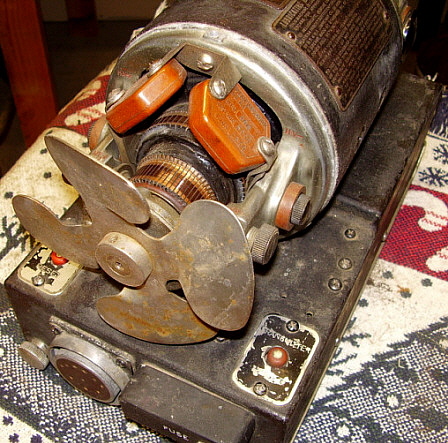
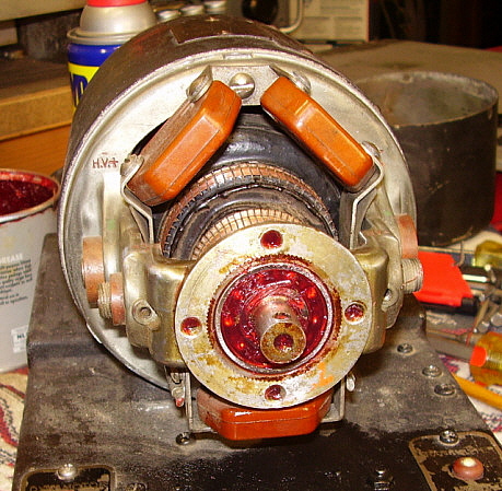
| | Dynamotor Details - Whatsoever versions of the Fine art-xiii transmitter tin be powered by whatsoever of the iv versions of dynamotor that were produced. The original ATC was supplied with the DY-eleven dynamotor. The T-47/ART-13 was supplied with the DY-12. All after ART-xiii transmitters used the DY-17 or DY-17A dynamotor. To ability any of the dynamotors requires using a shielded cable that uses two eight gauge wires that are connected to the dynamotor with a large 2-pivot Cannon plug and are then routed to the +28vdc power source. There is a pocket-size third pin for the shield in the original connector. The dynamotor more often than not requires about 32 amps at +28vdc at full output. The dynamotor is connected to the Fine art-13 via a shielded cablevision that utilizes two different types of Cannon plugs. The dynamotor-side uses a 10 pivot male plug and the transmitter-side uses a 10 pin female plug. All three of the original Cannon plugs are available for many sources (although they are not cheap!) Generally, the power cable has to exist built. The ART-13 power cablevision uses two 14 gauge wires (pins v & 6,) 5 18 approximate wires and two 16 gauge wires. These are the minimum gauge size that should be used. Larger wire sizes accept less voltage drop. I use 12 gauge for pins 5 & 6 and 16 approximate for the other seven wires and I utilize the centre conductor and insulation from a length of RG-58 coax for the +HV wire on pin ten. The ability cable has to exist shielded. I use the braid removed from RG-8U coax. Push button the coax shield together to expand its inner diameter and then sleeve it over the 10 wire cable. One time in place, pull the shield tight and wrap the entire cable with ii layers of electrician's record. Install the connectors and exist certain to connect the shield using a "bleed wire" to the connector shell on both ends. The ART-13 transmission volition have a schematic and breakdown of the the ability cable. Build the +28vdc cablevision in the same fashion. Use minimum of 8 guess wires (6 approximate is amend) and connect the shield to the pocket-sized pin of the connector. Be certain that the shield is connected to the negative of your loftier electric current DC power supply. The differences in the four versions of the dynamotors are locations of the reset switches which are on superlative of the base on the DY-11 and DY-12. The reset switches are on the front end panel of the DY-17 models. The finish bells differ on all 3 models with the DY-eleven having a circular screened vents, the DY-12 has vi spokes in its screened vents and the DY-17 has three spokes in its screened vents. Although there are some minor excursion changes between the models these changes don't affect how the dynamotors ability any of the Art-13 transmitters. >>> |
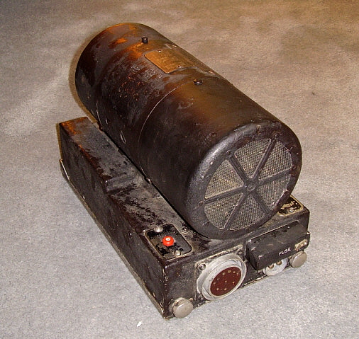
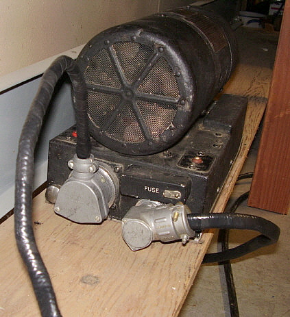
| >>> The photo above shows a DY-12 dynamotor which was originally supplied with the T-47/Art-xiii version of the transmitter. This particular dynamotor was congenital past Wincharger Corp. (aka Winco) and, although in kind of "rough" status, information technology does function correctly. The input and output box connectors are identical for all versions of the Art-thirteen dynamotors. The photograph right shows the DY-12 in service. This shows how the dynamotor connectors look. The DY-11 and DY-12 are difficult to find and usually are in original condition which means they may require some rebuilding to function well. The DY-17 is the more common version just it'southward still difficult to locate. Since most casual Art-xiii "parts collector-dealers" recall the DY-17 is the only proper dynamotor, information technology is usually the most expensive one to purchase, if it tin be found. Aforementioned holds truthful for the later DY-17A. In all cases, any newly purchased dynamotor should be serviced earlier using. Another word of circumspection on dynamotors in general,...dynamotors may be establish that take problems that tin't easily be repaired. A shorted armature might require rewinding and, if you lot can detect anyone to exercise it, the costs will be staggering. A recent quote to rewind a DY-17A armature was $3300 from a rebuilder in Los Angeles! If yous want to become the dynamotor route, attempt to arrange a test of the unit of measurement prior to purchase to encounter if information technology will operate correctly when powering an Art-thirteen. Even with a shorted output-side armature, the dynamotor will rotate since the motor-side winding is okay making the tester retrieve the dynamotor works. Notwithstanding, under load (trying to operate an ART-13) the lacking dynamotor will "bog downward" and not rotate at speed due to the excessive load of the shorted armature and the Art-13. You must test the dynamotor actually powering up an Fine art-xiii earlier you know it's usable. The specifications for the input and outputs are every bit follows: Input: +27vdc at 32amps - with the aircraft aloft, the charging kiss was nominally running at +28vdc (sometimes slightly higher) and this is where the dynamotors work all-time. The +27vdc spec allowed for some voltage drop in the power cable from the dynamotor to the buss. Outputs: +400vdc at .750amps and +750vdc at .350amps Notation : Since the +750vdc is in series with the +400vdc to provide the +HV, the +400vdc has a current requirement that is double, that is current for +LV and current for +HV. Also, this is the electric current that the dynamotor can supply, not the current that the Art-13 requires. | |
Running the Dynamotor only on Batteries (not recommended) - Using two 12vdc deep-cycle marine batteries connected in serial to provide +24vdc for dynamotor/xmtr power is not recommended. The batteries will have to be kept charged in some mode. Charging pb-acid batteries in the firm or ham shack can be dangerous and certainly is smelly. Additionally, the batteries alone will only provide virtually +26vdc subsequently charging and the voltage will drop chop-chop as the transmitter/dynamotor is in functioning. In the airplane, the transmitter/dynamotor ran on a battery-charger system that provided an almost constant +28vdc while the airplane was aloft. This is where the ART-13 runs best. Typical power output using the dynamotor on just batteries volition be effectually 60W to 70W. With a charging system (+28vdc) ability output will exist around 100W. This is due to the speed that the dynamotor turns. The +28vdc turns the dynamotor at its rated RPM where information technology delivers the rated voltages. At lower battery voltages, the dynamotor speed drops so does the voltage forth with the transmitter power output.
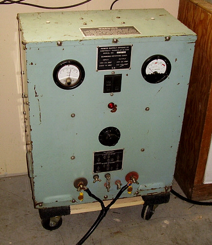
Running the Dynamotor with a High Electric current Air-conditioning PS (best solution) - To eliminate the batteries and run the dynamotor on a high-current +28vdc power supply is problematic due to the horrendous starting electric current required to operate the dynamotor. Although when turning at full speed (and powering the transmitter) the dynamotor load and the transmitter load requires effectually 35 amps, the initial starting current required by the motor section of the dynamotor is close to 100 amps. Although this starting current is very high information technology just lasts for a few milliseconds, that is, until the armature begins to move at which time the current need drops apace as the motor armature comes upwardly to speed. Even though the loftier current demand is for a very short elapsing, many modern, high current DC power supplies with current fold-back circuitry or other types of protection circuits will "see" the dynamotor every bit a "short circuit" and prevent the power supply from operating. The exceptions are some of the earlier military heavy-duty AC power supplies. These are early style "linear" supplies that can handle the surge current demand since it just lasts for a few milliseconds. The GRC-106 power supply is rated at +28vdc at 50Amps and, if one can exist located separated from the transceiver, it will operate the DY-17 (et al) dynamotors. Also, the heavy-duty "bombardment charger" unit, the PP-1104, tin can be used to supply +28vdc at well over 50A. These types of heavy-duty ability supplies can provide plenty current to start the ART-13 dynamotors. Too, there are portable aerodrome-type ability supplies used for starting airplane engines. These are available upwardly to 200 amps at +28vdc. However, "expensive" is an understatement. More details on the PP-1104 below.
Running with a Combination of Batteries and Hi-I AC PS (might be necessary in some cases) - Some other solution is to run the pb-acid batteries with an adjustable 0 to +50vdc ability supply capable of providing at least 20 to twoscore amps. That mode, you tin suit the power supply to have the battery system at +28vdc and simulate a charging organisation. The batteries will provide the 90 to 100 amps necessary for the initial starting electric current of the dynamotor. In essence, this combination simulates how the ART-xiii operated while on the aircraft aloft. This system may work with high current linear power supplies that have current fold-dorsum circuits, but experimentation would exist necessary since I oasis't tried that combination. Nevertheless, the hassle of running both batteries and a loftier current power supply seems to complicate a trouble that can exist easily solved by using either the PP-1104 or GRC-106 PS.
The PP-1104 was built for years past many dissimilar contractors. The Gladding-Keystone version I have is from 1967. The latest contract version I've seen was from 1989. With a petty searching, a PP-1104 should be pretty like shooting fish in a barrel to observe. The selling prices vary but look to pay around $200 to $300 for a decent ane.
| Curing RFI in the PP-1104 - Some PP-1104-C versions are rather noisy in the RF spectrum and the magnetic amplifier volition produce some RFI. These units can be set-upwardly with shielded AC lines coming in and shielded cables for the output. Be sure that the example of the power supply is also connected directly to the station ground system with a 10 ga. footing wire. Additionally, information technology's a expert idea to bypass the AC line in with .01uf capacitors to chassis and to likewise bypass both the positive and negative output terminals with a .22uf tubular and a .01uf ceramic deejay capacitors connected to chassis. Be sure to check the 10-32 screws that mount the top cover, the bottom and the back comprehend to come across if practiced grounding contact is being achieved. Commonly the pigment is very heavily applied and quite hard which insulates the covers from making practiced contact to the main frame. It's commonly necessary to employ a minor sanding deejay to remove the paint where each screw caput makes contact and remount the screws using toothed lock washers. This will provide an "RF tight" enclosure which helps considerably in reducing RF noise. Thanks to Jerry W6JRY for the PP-1104 RFI suggestions. Operation - Using the PP-1104 to operate dynamotors eliminates most of the headaches since the power supply is capable of providing the starting current without hesitation. Likewise, since the PP-1104-C can be adjusted to over 40vdc output voltage, adjusting to 28vdc under load is easy and allows the ART-thirteen-dynamotor combo to run efficiently and with maximum RF output power (100 to 110 watts typically.) Y'all might find that the unloaded voltage (when you're non transmitting) might be a fiddling high running up to maybe 30vdc merely it is possible to adapt the PP-1104 to find the best compromise of loaded versus unloaded atmospheric condition. You shouldn't adjust the PP-1104 when information technology is operating, and then some experimenting will exist required. Also, if you employ the largest gauge wire that will fit in the connector sockets in your Fine art-13 to Dynamotor cablevision and the PP-1104 to dynamotor cable, the less voltage drop yous'll experience and thus the less voltage change between load and no load conditions. Typical excursions with big gauge wires in your cables is between 1vdc and 2vdc maximum. Usually, you lot can set the PP-1104 for +28.5vdc no load and under load the voltage will be +27.5vdc, which is ideal. Remember that the ART-13 tube filaments are running on the PP-1104 in both transmit and receive, so endeavor to go along the supply voltage as close to +28vdc nominal equally possible. photo right : A 1967 PP-1104-C built by Gladding-Keystone Corp. A little flake scratched upwards just nevertheless working fine. Annotation that the voltage meter (left) is a replacement meter. As well, notation the small moving dolly used for piece of cake relocation of this heavy power supply | |
Servicing the ART-xiii Dynamotors
This write-up relates the servicing procedure (with photos) of the DY-12 version of the Fine art-thirteen dynamotor. The servicing procedure is the same for each of the ART-13 dynamotor versions. There will exist slight differences in cease bells and the base but, internally, the DY-11, DY-12, DY-17 and DY-17A, are the same.
| Most of the dynamotors we encounter haven't been serviced in a very long fourth dimension. Maybe the original grease is still in the bearings. You never know until you have the dynamotor apart and check. Generally, if you lot remove the finish bells yous can access virtually of the areas of interest. Yous'll desire to check the following: 1. Condition of the brushes 2. Condition of the commutator segments 3. Type and amount of grease in the bearings Remove the brushes to check length and the surface that contacts the commutator. You will have to remove all of the brushes even if the brushes are in good condition considering of the cleaning solvents used to remove the old bearing grease could contaminate the brush surface. Keep the brushes make clean by removing them earlier the cleaning procedure. The brushes are marked "+" and "-" for proper location. The dynamotor frame too is marked "+" and "-" and for "MV" and "HV" to aid in proper brush location. Also, the brushes are usually inserted with the "+" or "-" facing upwardly. The brushes should fit the contour of the commutator. The brushes should as well be long enough to non run hot. Usually about 1/iv" minimum above the bottom edge of the housing is okay. If the brushes are too brusque so they should be replaced with new brushes. If the brushes need replacing so you'll probably have to go to a motor rebuilding shop or other source of brushes to find a set up that are the right dimensions. Unremarkably, the original brushes are okay because the war machine serviced the dynamotors when they were in use and when the dynamotors went to surplus they were never used again. Consequently, the brushes are unremarkably in decent condition. If you practice purchase new brushes they will accept to be contoured to fit the commutator closely. This can unremarkably be accomplished with fine sandpaper that is placed around a wooden form that's the same bore every bit the commutator. The goal is to have the brush surface perfectly match the shape of the commutator. This will reduce brush wear and eliminate "sparking." | |
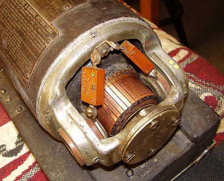
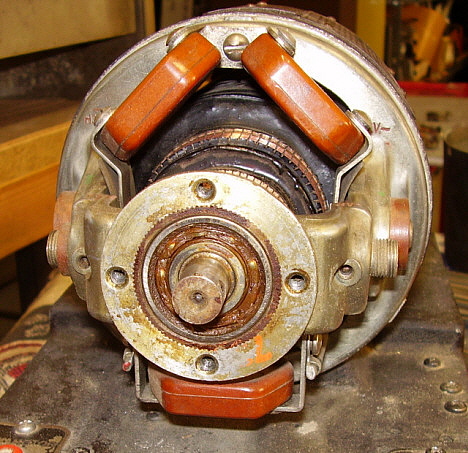
| | The commutator segments should exist bright and smooth and not exhibit any grooving or vesture. Light cleaning can be done with very fine sandpaper held confronting the segments while the armature is rotated by hand. The photograph above shows how the commutators looked on this DY-12 before cleaning. Most of the time, the low-cal cleaning is all that'southward needed. Once more, the dynamotors were maintained in the war machine and afterwards seldom, if ever, used. Be sure to clean the grooves between each segment after the light cleaning. Sometimes conductive residual tin become into the grooves and crusade bug. Clean with denatured alcohol and an acid brush. The fan should be removed for meliorate admission to the +HV and +LV commutators. The set screws have to be almost withdrawn from the fan hub since the shaft has recessed holes for the prepare screws. Also, on the +HV and +LV side, removing the top two bypass capacitors volition requite better access to that commutator. The ball bearings will normally need some attention. Again, while in the armed forces, they were greased when the dynamotor was serviced, but since then, they have probably never even been inspected. You'll usually detect that there is grease present but it has hardened to the signal of condign wax or even harder. Ordinarily though, the old, hard grease volition soften when saturated with WD-40. Use WD-40 equally a solvent to spray the bearings. Use an acid brush or small potent paint brush to work the WD-40 into the bearings. This should clean out virtually, if not all, of the old grease. The brawl bearings should spin freely at this point. Photo below left shows the original grease earlier repacking. At present, work new grease into the ball bearings. Don't apply that quondam, stringy, xanthous grease that the military used back in the 1940s (even if you could discover it.) Use modern loftier temperature wheel bearing grease. This type of grease is piece of cake to find at whatever place that sells automobile parts and is usually transparent red. Use your thumb and fingers to "press" the new grease into the ball bearings until they are well-nigh total. Replace the gaskets and covers. Be sure to clean and install whatsoever shims that adjust the thrust movement of the armature. Photo below right shows the bearing with new grease before the cover was reinstalled. |
| Since yous've repacked the bearings, clean the commutators with alcohol again to make sure there's no grease on the segments. Supplant the brushes and brush retaining caps. If you've marked the orientation and location, everything should go together hands and correctly. Install the end-bells. You might have to clean their mating surfaces for easier installation. Connect the dynamotor to a voltage source and to the Art-13 for a load. Upon switching on power and actuating the PTT on the Fine art-thirteen, the dynamotor should rapidly come up to speed and power upwardly the Fine art-13. The bearings should exist running quietly,...well, as tranquillity as a large dynamotor runs anyway. If everything is correct, the Art-13 should produce a piddling over 100 watts output when running on a good status dynamotor (that's powered by a PP-1104-C or similar power source.) When PPT is released the dynamotor should "declension" to a finish in a few seconds. This shows that the brushes are riding smoothly and the bearings have aplenty lubrication. | | |
For more details on cable building and operating the Fine art-13 with a dynamotor go to "Operating the T-47/ART-13 with the DY-12 Dynamotor" further down this page
____________________________________________________________________
Donations to Radio Boulevard - Western Historic Radio Museum'due south Website
If you enjoy using Radio Boulevard - Western Historic Radio Museum'south website as an information resource and take found our photos, our difficult to notice data or our restoration articles helpful, then delight consider a donation to the WHRM website. A small donation volition aid with the expenses of website operation, which includes website hosting fees, data transfer fees, research, photographing and composition. WHRM was a existent museum that was "Open up-to-the-Public" from 1994 to 2012 - eighteen years of functioning. WHRM will go along to provide its on-line information source with this website, which has been in operation since 1997.
Delight employ PayPal for sending a donation by clicking on the "Donate" Push button below
______________________________________________________________
Radio Boulevard
Western Historic Radio Museum
Vintage Radio Communication Equipment Rebuilding & Restoration Articles,
Vintage Radio History and WHRM Radio Photograph Galleries
1909 - 1969
- 60 years of Radio Technology -
This website created and maintained by: Henry Rogers - Radio Boulevard, Western Historic Radio Museum � 1997/2022
Source: https://www.radioblvd.com/art13.htm